
Technology
技術分享
Overview of Civil, Structural and Architectural Engineering for the Kaohsiung MRT Yellow Line
— Kuei Chen, Design Engineer at CTCI Resources Inc., Group Intelligent Business
Mass Rapid Transit (MRT) systems are indispensable components of urban transportation, and the design and construction of underground MRT stations require highly integrated multidisciplinary engineering expertise. CTCI Group has long been dedicated to the field of transit engineering, having participated in the construction of most MRT lines in Taiwan and successfully expanding its track record overseas to Singapore. Among its Group companies, CTCI Resources Engineering Inc. (CTCI REI), has actively participated in and contributed to the civil and building engineering of MRT projects in Taipei, Kaohsiung, and Taoyuan. This article introduces how CTCI REI helps the client build a benchmark city for green transportation through a combination of multidisciplinary expertise in the civil engineering project for the Kaohsiung MRT Yellow Line, ensuring durability and cost-effectiveness in spatial layout, structural safety, and deep excavation engineering.
Project Introduction
Spanning approximately 23 kilometers, the Kaohsiung MRT Yellow Line passes through multiple administrative districts, including Niaosong, Fengshan, Sanmin, Lingya, and Qianzhen. The line comprises one elevated station, 22 underground stations, and one depot. The overall civil engineering is complex not just because of the operational, safety, and construction requirements for the line per se, but also the necessary interface integration work to ensure continuous operation and relocation of underground utilities, such as water mains, electricity, and gas lines. In this project, CTCI REI is primarily responsible for the civil works design of six underground stations: Y8, Y13, Y14, Y15, Y17, and Y18.
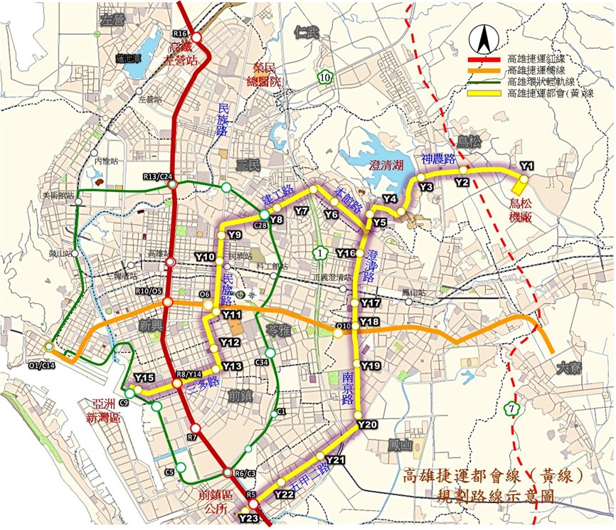
Kaohsiung MRT Yellow Line Network Map
Architectural Design
Architectural design, which determines passenger experience and safety, is the key element of an MRT station. The core tasks of architectural design lie in spatial layout, circulation planning, emergency evacuation review, artistic and cultural expression, and urban interface integration.

Facility Capacity Planning:
Station spaces are calculated based on the "Passenger Volume during Peak Hours of the Target Year." This includes the widths of the concourse and platform levels, the number of automatic fare collection machines and ticket gates, and the arrangement of vertical circulation (elevators and escalators), all of which must satisfy passenger flow demands.

Emergency Evacuation Verification:
In the event of an emergency, all passengers inside the station must be able to evacuate safely within a specified time limit via stairs, escalators, and walkways. Taking Station Y17 as an example, under emergency conditions, all passengers on the platform level can clear the platform within 4 minutes and reach the ground-level safe zone within 6 minutes.

Station Interior Spatial Layout:
In addition to the public areas traversed by passengers, the station accommodates staff rooms and numerous technical equipment rooms. The overall spatial layout is planned according to the operational requirements of the MRT system. Because the sizes and positions of each space are interdependent and station space is limited, the overall spatial utilization must be meticulously planned during design to fulfill operational needs.
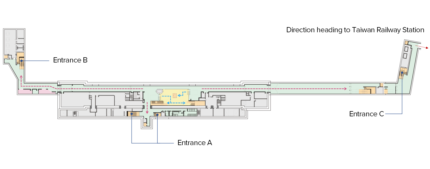
Schematic Diagram of Station Interior Spatial Layout
Architectural Expression and Aesthetic Design:
The theme of an MRT station’s aesthetic design typically draws from natural or cultural elements surrounding the the station, as a way of blending the public transit facility into the local environment. For instance, Station Y18 is adjacent to the National Kaohsiung Center for the Arts (Weiwuying). Therefore, the architectural finishing of the station entrance references the Weiwuying architecture, using a curved roof profile as the primary design motif to maintain the harmony and beauty of the area's overall landscape.
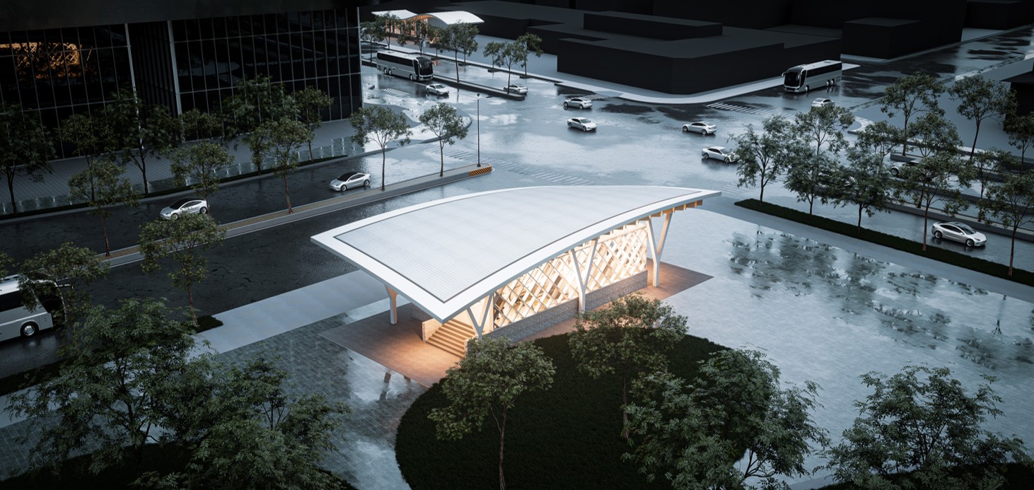
Conceptual Rendering of Entrance C, Station Y18
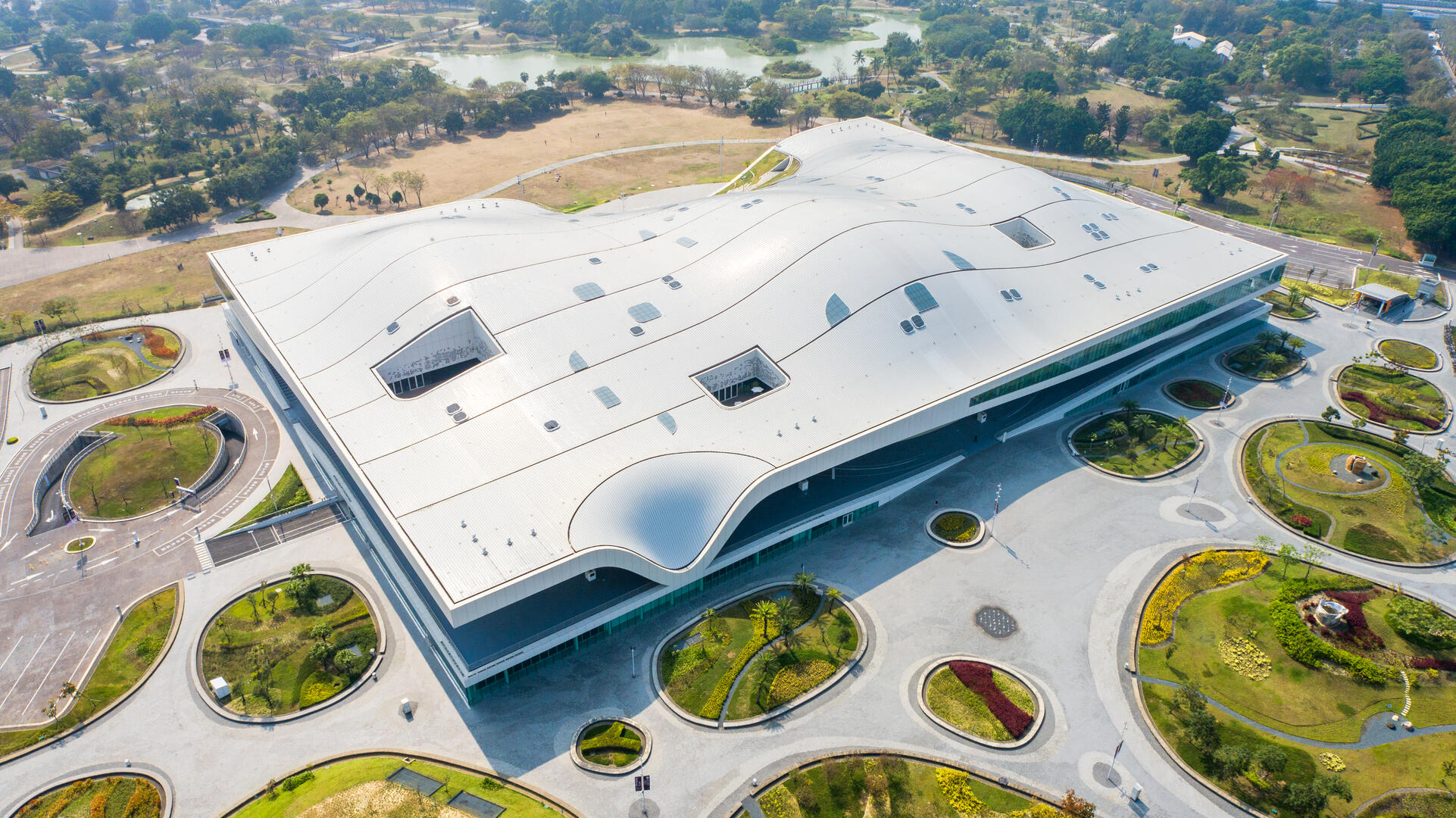
National Kaohsiung Center for the Arts (Weiwuying)
External Interface Integration:
Taking Station Y17 as an example, a  pedestrian underpass connects the MRT station with the Taiwan Railways Zhengyi Station, allowing passengers to complete seamless transfers underground, vastly improving convenience. Beyond standard transfers, joint development projects will be implemented at Yellow Line stations Y8, Y15, and Y18. Their entrances will be co-constructed with commercial office buildings to stimulate local industry and economic development while enhancing passenger convenience. Therefore, when designing the station, it is necessary to coordinate with joint development investors to incorporate these factors into the overall architectural and structural design.
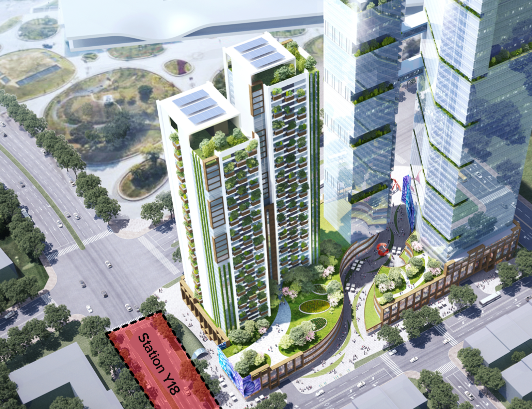
Simulation Rendering of the Station Y18 Joint Development Project
Structural Engineering Design
The design of underground station structures must account for the pressures exerted by soil and groundwater, as well as the challenges posed by seismic activity.

Structural Type:
The Kaohsiung MRT Yellow Line stations utilize concrete box structures with slab-and-wall systems, which offer excellent resistance against earth pressure, external loads, and seismic forces. Stations typically employ a double-wall system consisting of a diaphragm wall combined with a permanent internal wall to enhance waterproofing performance. Where land for entrances is restricted, a single-wall system is partially adopted, incorporating the diaphragm wall directly into the permanent structure. However, this approach requires rigorous construction quality and precision control to ensure waterproofing performance and the corrosion protection for rebars.

Seismic Considerations:
Racking analysis is adopted for underground structure seismic analysis, taking into account soil-structure interaction. Two-dimensional finite element analysis is utilized to evaluate the deformation and stress relationships between the soil and the structure. Subsequently, three-dimensional analysis is applied to evaluate stress concentration behaviors in irregular or perforated structures, ensuring overall seismic safety and design rationality.

Waterproofing:
There are three watertight grades: Grade A, Grade B, and Grade C. For Grade A, the structure must be free of leaks or damp patches. For Grade B, damp patches are permitted on joint surfaces, but no visible leakage or running water is allowed. For Grade C, seepage is permitted but restricted to damp patches on construction joint surfaces or water run-down along vertical construction joints. Station roof slabs are required to be Grade A watertight, while base slabs and external walls are Grade B, while sump pits are Grade C. Waterstops and waterproofing membranes are incorporated into the design to reinforce water tightness.

Interface:
If the difference in settlement between two underground structures is significant, or if the difference in structural stress is significant due to different structural systems (such as the main station structure versus entrance structures), it is generally treated with expansion joints .
Geotechnical Engineering Design
Underground station often involves deep excavations of 20 to 30 meters. It is therefore a substantial objective of geotechnical engineering to ensure that the excavation process does not cause surrounding road collapse or damage to adjacent buildings.

Excavation Shoring and Retaining System:
In principle, the stations and entrances of the Kaohsiung MRT Yellow Line utilize reinforced concrete diaphragm walls as the earth retaining and shoring structures. Characterized by high stiffness, they effectively suppress lateral displacement and reduce ground settlement. The design relies on the diaphragm walls and internal strutting systems to collectively bear earth pressure, water pressure, and external surcharges. During construction, joint quality is strictly controlled to ensure water tightness. The strutting system, meanwhile, is densely configured and appropriately pre-stressed to effectively control deformation, ensuring the stability of the entire retaining system and the safety of the surrounding environment.

Shield Tunnel Segment Design:
To form shield tunnel linings, precast arch-shaped segments are assembled into rings within the shield tail of the Tunnel Boring Machine (TBM). The shield tunnels in this project have an internal diameter of 5.6 meters, and the concrete segments serve as both temporary support during tunnel excavation and the permanent tunnel lining. Segments are connected via bolts and fitted with hydrophilic waterstops to prevent water ingress. Segment design must consider not only geotechnical characteristics but also earth and water pressures, existing and future surface structural loads, traffic and MRT live loads, and construction loads such as grouting pressure and TBM thrust.

Monitoring System:
To ensure the safety of temporary and permanent structures , adjacent buildings, roads, and the construction site during excavation and shield tunneling, instrumentation are placed within the soil layers and structures to monitor construction-induced settlement, ground displacement, pore water pressure variations, and structural stress/strain states.
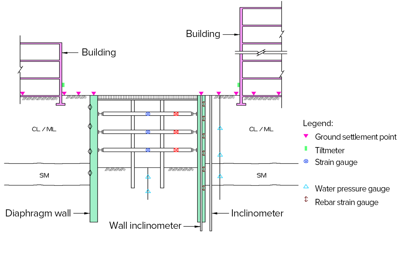
Schematic Layout of Instrumentation for the Cut-and-Cover Construction Method of Underground Stations
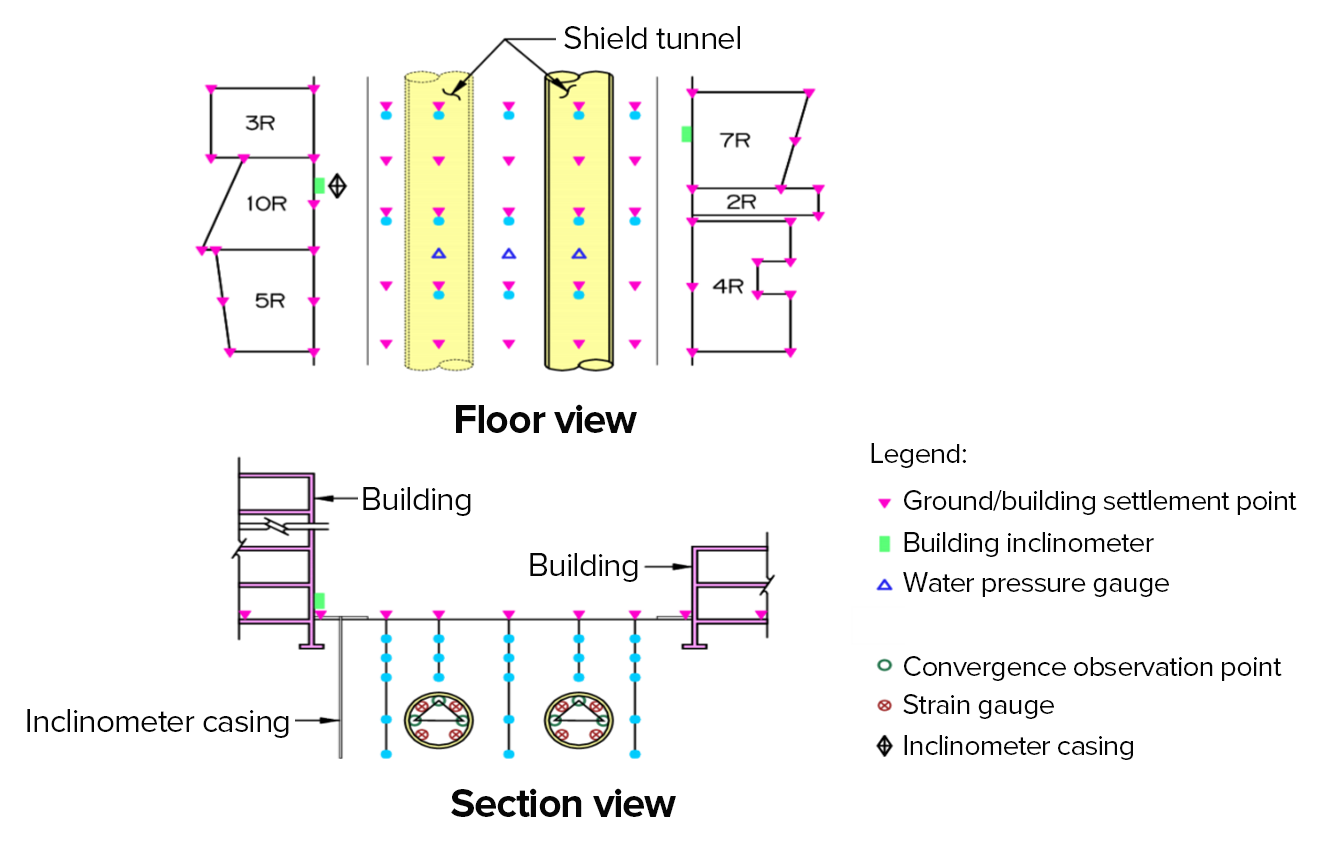
Schematic Layout of Instrumentation for Shield Tunnel Construction
Protection Measures for Adjacent Buildings:
To reduce lateral deformation of diaphragm walls and ground settlement, appropriate earth retaining system and strutting configuration are selected based on building structural types, foundation types, and geotechnical conditions. If, according to assessment, the settlement values might exceed a building’s allowable threshold, supplementary reinforcement measures are deployed. These include increasing strut pre-stress, adding strut levels or horizontal strut components, installing buttresses on the inner side of the diaphragm wall, or using chemical/high-pressure jet grouting to enhance ground stiffness and minimize ground deformation. If the building is a historical site, a key protected structure, or exhibits an existing tilt angle exceeding 1/300, additional protective measures will be deployed. One example is to increase the strut pre-stress to a specific percentage of the maximum axial force to reduce wall deformation during shallow excavation stages. Another example is to install tiltmeters and settlement gauges to increase monitoring frequency and enhance early-warning control.

For protection of adjacent buildings during shield tunnel construction, the construction team would estimate the value of ground settlement based on the geological characteristics, loading data, and past construction records. If the estimated value exceeds the building's allowable deformation, protective measures are deployed, such as secondary grouting from within the tunnel or ground improvement grouting from the surface, thereby stabilizing the ground and reducing the displacement of adjacent structures.
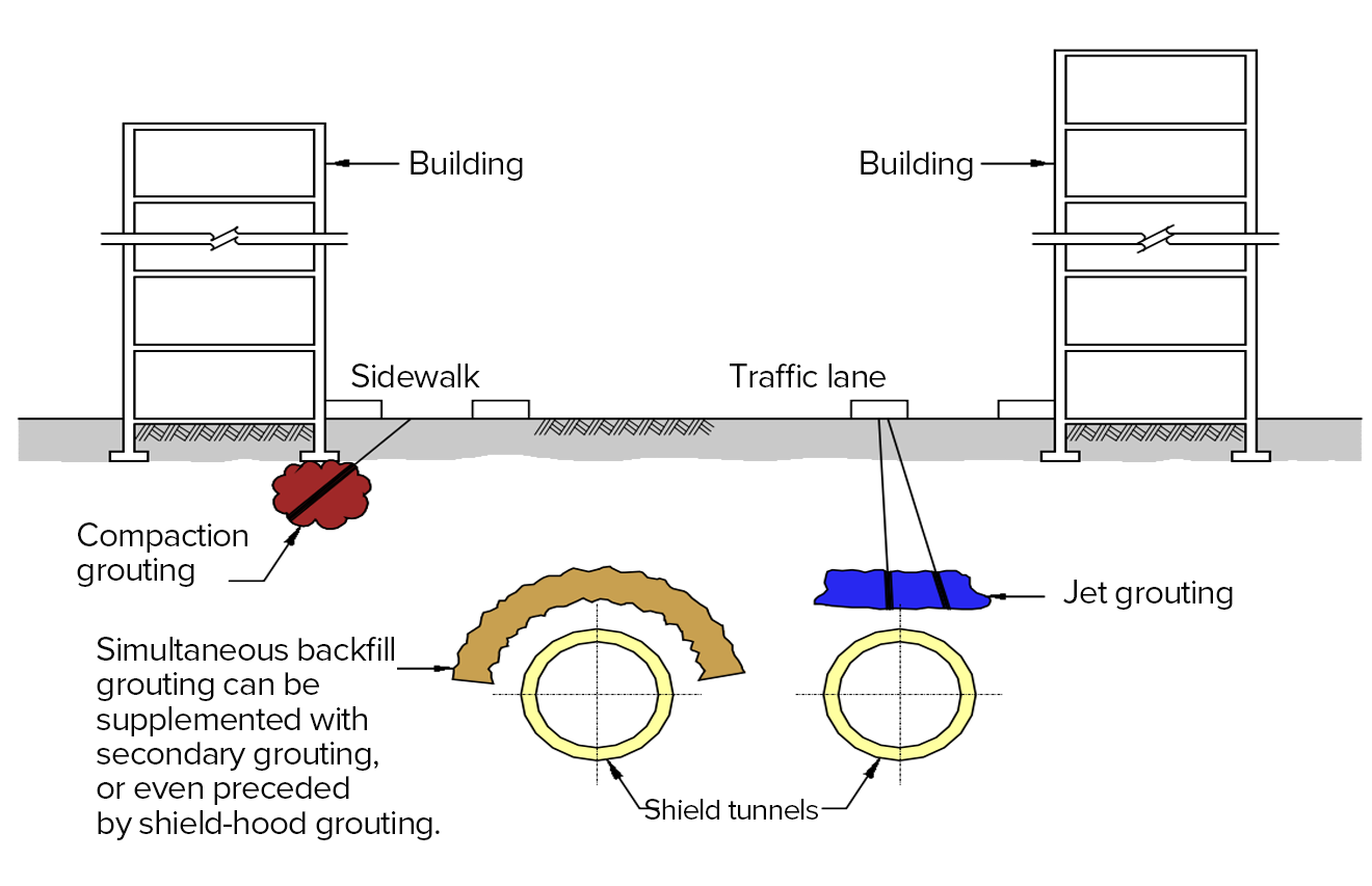
Schematic Diagram of Common Building Protection Methods Used in MRT Shield Tunnel Sections
Utility Relocation Engineering
MRT stations are mostly located beneath public roads rather than within standard residential or commercial plots. Consequently, the subsurface of the work zones is densely packed with utilities, including water mains, power lines, telecommunications, gas, and stormwater/sewer pipes. It is a major challenge in MRT projects to properly manage these utilities to facilitate smooth station excavation.

Utility Relocation Planning:
Prior to diaphragm wall construction, large-scale utility diversion works must be carried out. This requires coordination with various utility authorities to plan "temporary diversion" and "permanent reinstatement" routes. Some utilities, however, need to be suspended across the station excavation zone due to land availability restrictions or operational demands. In that case, the excavation shoring and retaining system must be redesigned to accommodate the positions and loads of these suspended utilities.

Maintenance of Utility Operations:
During construction, it is imperative to ensure that electricity, water, and telecommunication services to surrounding buildings remain uninterrupted. The relocation positions of various utilities must be meticulously planned within the highly constrained spaces of the construction fences.

Taking Stations Y17 and Y18 as examples, a major water main with a diameter of 2.2 meters traverses above the stations. During construction, this pipe is suspended within the excavation zone while maintaining water flow. The positions and load considerations of the diaphragm wall's horizontal struts and plunge columns are designed in alignment with this water main, ensuring that the public water supply remains unaffected throughout construction.
Conclusion
In summary, the civil and building design of the Kaohsiung MRT Yellow Line requires the integration of multiple professional disciplines, including architecture, structural engineering, and geotechnical engineering. Leveraging its extensive experience in MRT civil engineering, CTCI REI assisted the client in completing such highly challenging and complex project safely, efficiently, and cost-effectively.


