Technology
技術分享
Case Sharing—Research and Discussion on Fire Protection Design and Construction Planning of Super High-Rise Buildings
— Phil You, Mechanical Engineering Department, CTCI Smart Engineering Corporation, Group Intelligent Solutions Business
With the progress of the time, the degree of urbanization in various parts of Taiwan has been increasing, making the acquisition of land in these areas more difficult and expensive. Under the current laws and regulations, to pursue the maximum land use efficiency, buildings are getting higher and higher with deeper foundations to meet the demands for the coverage ratio and floor area ratio. However, when accidents occur, providing disaster relief becomes more and more difficult. With the increasing number of supertall buildings, it is important to improve the safety of buildings through a solid emergency response plan to ensure the safety of residents.

In this article, we will use Taichung congregate housing project contracted by CTCI Smart Engineering Corporation (CTCI SEC) of Group Intelligent Solutions Business as an example, and explore its firefighting system design and construction planning.
The definitions of super-high-rise buildings and their fire prevention needs
Owing to the height of super-high-rise buildings (please refer Table 1 for definitions), when the fire occurs, it is difficult to carry out rescues from the outside these buildings. Therefore, the key point to their fire emergency design is how to quickly complete evacuation and fire rescue when fire emergency occurs.

First of all, the building must have complete self-rescue equipment, and escape and evacuation design to ensure safety. In the architectural design stage, while planning the zoning and floor insulation (e.g., the fire-resistance of pipelines and pipe penetrations), the restrictions of the materials should be considered as selecting the fire-resistant and interior decoration. When the fire emergency occurs, such planning would stop the fire from spreading to other floors without damaging the integrity of the structure. The fire prevention and extinguishing equipment includes fire extinguishers, indoor fire hydrants, water spreading systems, and water delivery systems for firefighting. The escape and evacuation facilities include safety ladders and special safety ladders, safety floors and evacuation spaces, emergency lighting and smoke evacuation equipment, etc.
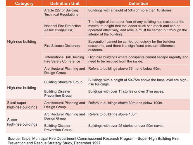
The definitions of high-rise, semi super-high-rise, and super-high-rise buildings.
Case sharing: emergency evacuation design and construction process in a congregate housing project in Taichung
The building in this case is built in a steel reinforced concrete (SRC) structure with a total floor area of 68,501.16m², 6 floors underground, 41 floors above ground, and 3 floors for the penthouse with a steel structure (steel construction, SC) and exterior glass wall. During the fire protection performance review, the committee has requested that the working balcony of each unit be used as space for emergency evacuation (see Figure 1 below), with separate fire compartmentation and automatic fire sprinklers. In terms of the needs of the people who are physically challenged, two additional waiting spaces for rescue purposes were set up within the smoke lobby in front of the special fire escape ladder at each floor.

In construction planning, the goal is to block the vertical spread of fire. We separated fire through zoning of each floor with fire compartmentation and reduced pipe shafts that break through different floors. Beside the necessary vertical shafts such as public staircases and lifting equipment, the electrical and mechanical pipe distribution pipes adopted fire-resistant construction materials and tubes with fire-resistant fillers. In the house, the floor for bath/toilet is descended, and the floor pipe is reinforced with 60cm high RC supplemented by an expansion ring to stop the fire from spreading (see figure 2).
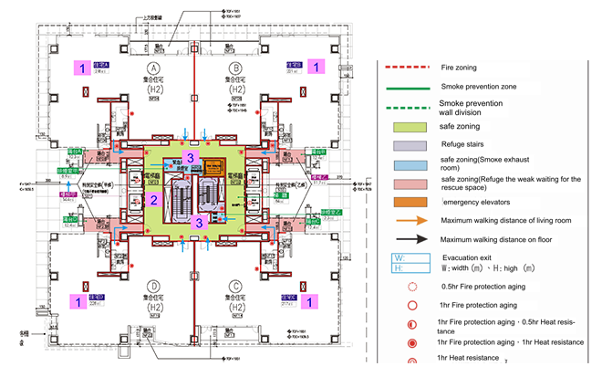
Figure 1. Typical floor fire zone.
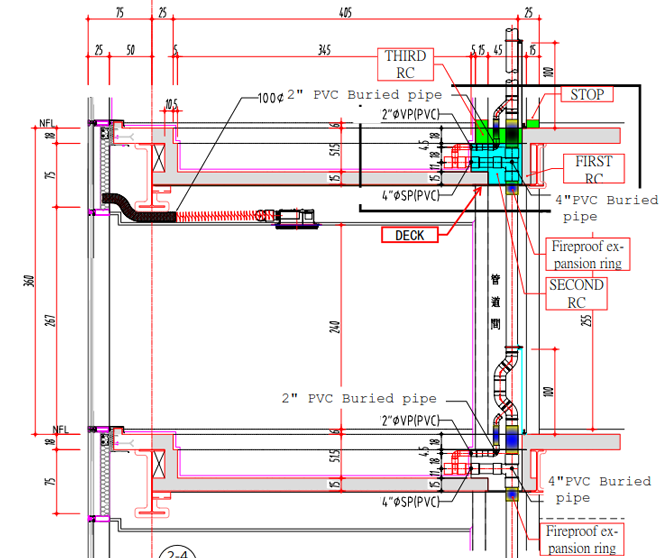
Figure 2. A section view of the descending floor of the bath.
Descriptions below are the system configurations in this case:
1. Configurations of the four fire pump rooms located in B6F, B2F, 15F and R1F are introduced below.
(1) B6F: 5 systems, including foam pump, fire pump, automatic sprinkler pump, fire water pump and water spray sprinkler pump are installed.
(2) B2F: A connecting pump is installed.
(3) 15F: 3 systems, including relay hydraulic pump, relay sprinkler pump and relay connecting pump are installed.
(4) R1F: 2 systems, including relay sprinkler pump and relay connecting pump are installed.
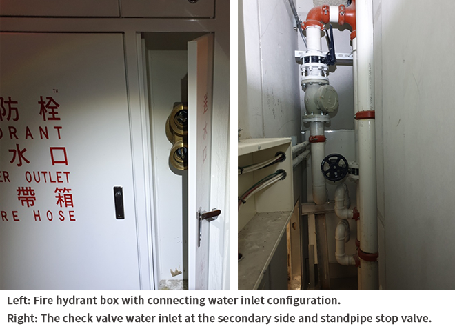
2. Fire hydrant connection system.
The design of the hydrant connection system in this case is to position the connecting water inlet at the first floor outdoors within the building line area, which is then connected to the B2F fire pump room through piping, and pumped by connecting the water pump to relay room at the 15F. Then, the relay connecting pump at the 15F will deliver the hydrant water via series operation mode to the relay connecting pump at the R1F to elevate water pressure with pump series for fire extinguishing at higher floors .

For the conventional fire design, the fire hydrant pump room should be configured every 50 meters. In this case, the fire hydrant pump room should be set at the 15F and 30F. However, because of the vibration and noise associated with the rotating equipment in the pump room, it is often regarded as an unwanted facility, resulting in the floor where the pump room is located and its lower floor being unpopular. Therefore, most commercial buildings will avoid positioning the fire hydrant pump room at the middle floor. For this project, at the beginning of the design stage, the design of this project was based on the principle of reducing the number of relay pumps in the middle floor, and the design was approved as equivalent to the regulatory requirements. The pump room has been positioned at the R1F instead of 30F to increase the value of the building in the market.

In the case, the fire hydrant pump room on the high floor was rearranged to the roof floor. When the connecting water pump at the 15F is out of order, mobile fire pumps will be used to transport hydrant water. The suction end of the mobile pump is connected with the water outlets at the planned transferring floors and the suction end of the pump is connected to outlets of the transferring floors to pump the water upwards. The transferring floors are configured at the 20, 24, 27, 31, 35 and 39F, respectively, and a water outlet, a gate valve, a reverse stop valve, and stop valves which are installed between the hydrant and the outlet of the standpipe are adding additionally to each floor. When an emergency occurs and hydrant water transport is needed, the water stop valve on the standpipe is closed to avoid failure to transport water upwards due to short circulation , thus ensuring that the floor where emergency occurs can properly handle the fire with enough water pressure. After the fire is extinguished, the water valve on the main standpipe will be opened to restore the system to normal operations.
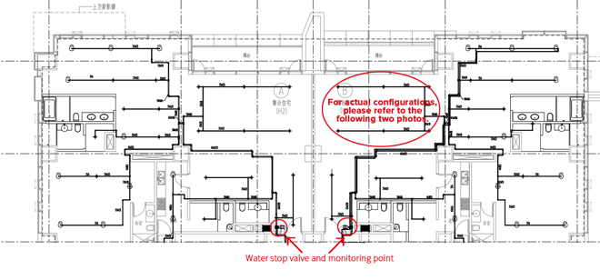
3. Automatic sprinkler system
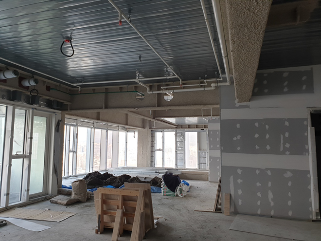
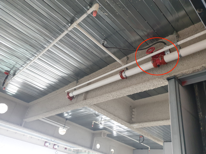
As a high-class congregate housing project, its water sprinkler system design is different from general congregate housing. Specifically, every household is equipped with a stop valve at the door side with a monitoring point in place (refer to the sprinkler system floor plan below). This makes it easy for any single household to perform renovation work without affecting the entire sprinkler system of the whole floor by just shutting down the stop valve of the house. There is no need to shut down the automatic alarm check valve of the whole floor.

In addition, to create an even better living experience and the visually appealing view for the residents, the owner required the CTCI project team to reserve more space when making the automatic water sprinkler piping configuration plan— maximizing the ceiling height for decoration. With this aim, the distribution of pipe shall not occupy the beamless area. Pipes are fitted alongside the beams after penetrating the beam when entering the house area. By this way, the residents only need to wrap the beams and the ceiling height for the beamless area to be elevated when they are remodeling the house. In fact, this operation is not in the original design. However, the effort to redesign the operation with beam penetration of pipes required extra safety consideration and had to take into account the position of the steel beam opening and reinforcement of plate application and space. This not only consumed more time of the design work, but also increased the difficulty of construction. In addition, to match the more curved pipe path, our team increased the pipe length, used more pipe segments and elbows for connection, increasing the difficulty for pressure tests and leakage risk.
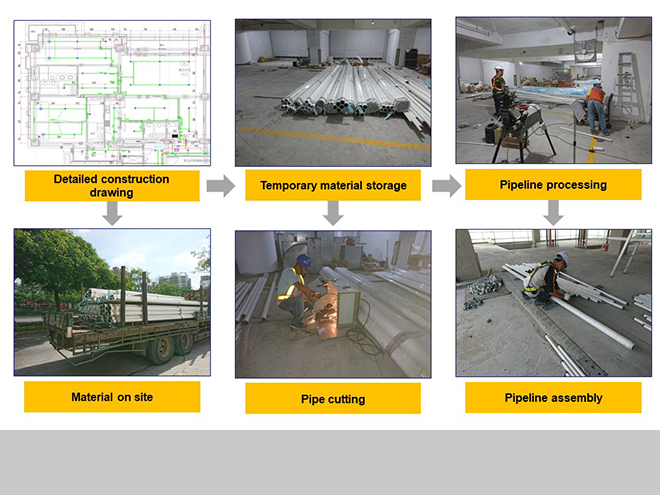
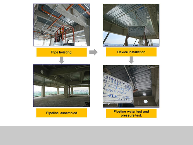
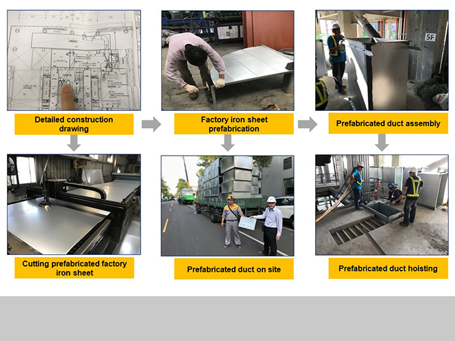
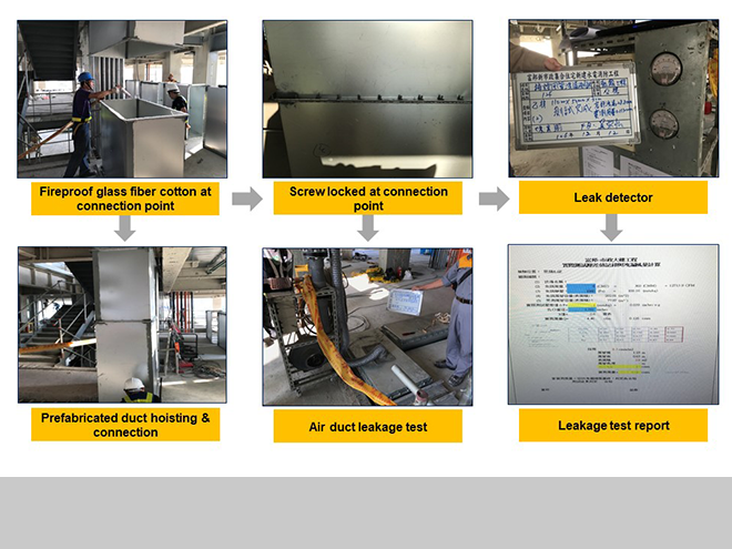
Moreover, since the project in question is a congregate housing, with an analysis of the project building map and structural map at the initial phase, we noticed that the building configurations for typical floors shared a similarity of up to 80%. Taking into account this characteristic, we embarked on the "standardization" concept for the sprinkler pipe. We integrated the system plan configuration, and decided for the sprinkler pipe beam penetration design with priority given to complete the typical floor integration. According to the advice from the owner, we performed a mock-up at the 5th floor for testing and confirmation purposes. Under such standardized planning, not only can the loss in pipes be reduced, but also there is no need to review, make overlay mapping and collision inspection on each floor due to their identical configuration. Only when discrepancies are found, are the partial corrections required. The flowchart below is accompanied by construction photos.
4.Smoke exhaust system at the special refuge stairways
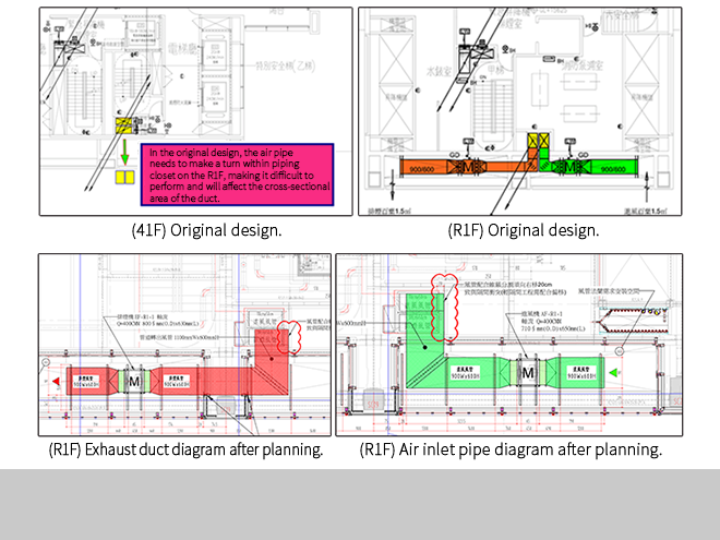
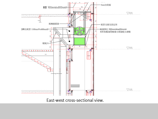
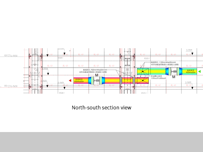
Given the fact that a super-high-rise shaft pipe is utilized in this project, mechanical flanges are used to fasten the duct and therefore construction space becomes an issue. As the underground pipe was originally a RC (reinforced concrete) wall, after reviewing and coordinating with the civil interface contractors, we adopted construction that is less complicated and lightweight grout mixture wall instead. Construction work was initiated from the windpipe, followed by connection between the duct and the fan, with careful consideration.

Finally, the sequence between the ducts and the pipe winding also poses challenges. The original design was to make a turn for pipes between 41F and R1F. However, the original duct design at the 41F is an up-and-down configuration, while at the R1F, it turned into a different side-by-side configuration, making pipe winding operations unworkable. To solve this problem, when drawing the construction blueprint, we noticed that there is no air intake and exhauster gate configuration in the piping closet. We changed the air pipe configuration taking advantage of the height difference to step over the external wall to connect the exhaust fan. Since there is a grille outside the fan, it would not affect the appearance. This adjustment was also permitted by the owner, and has saved us the hassle of having to carry out work by sticking to the original design. The flowchart below is accompanied by construction photos.
Conclusion
When fire protection design for super-high-rise buildings is concerned, performance-based fire safety design can be utilized to attend simultaneously to the requirements of regulations and the needs of the owners if the site conditions cannot comply with the standard fire safety code. Considering the efficiency and quality of construction, we leveraged the characteristics of congregate housing and pre-fabricated facilities like the sprinkler system and smoke room system with shared configuration for typical floors, which accounted for the highest proportion of the housing project. By doing so, not only can we apply the standardized construction concept, but we can also be spared the work of applying differentiated design for each floor, greatly reducing construction issues and shortening the construction schedule with greater benefit.