Technology
技術分享
Application of Cleanroom Technologies and Computational Fluid Dynamics
— Ming-Fu Wu, Engineer at Mechanical Department, CTCI SEC
Cleanrooms are widely utilized in industries with production processes highly sensitive to environmental pollutions, such as the electronics, pharmaceuticals, biotechnology, precision machinery industries, hospitals, and food producers. For the highly competitive semiconductor industry in particular, cleanroom is an indispensable facility. Major technology companies are now actively investing in the research and development of more advanced processes to maintain their competitive edges in the fierce global market. As production technologies and processes continue to advance, requirements for equipment and environment become more demanding. The biggest challenge now engineering companies need to tackle is to think a way to create a clean production environment in a very short time span that can meet the needs of advanced manufacturing processes and the increase of production yield.

Given the current state of technologies, dust particle control is no longer a difficult task for cleanroom projects. High-grade cleanrooms today not only have vigorous requirements for dust particles, but also become ever demanding in terms of temperature, humidity, vibration, and chemical pollution. Particularly demanding for the semiconductor industry are the requirements for airborne molecular contaminants (AMC), temperature, humidity, and vibration. This article explores future cleanroom engineering trends as well as some practical applications of real-time monitoring, automation systems, and computational fluid dynamics (CFD) through a case study of 8K thin film transistor liquid crystal display (TFT-LCD) panel factory, which was jointly carried out by CTCI Smart Engineering Corporation (CTCI SEC) and CTCI Shanghai Co., Ltd. (CTCI Shanghai).
Introduction to Cleanrooms and the Current State of the Industry
A "cleanroom" is a room with special design that can help remove various air pollutants such as micro particles, harmful gases, and bacteria from the rooms. Through control of room temperature, humidity, cleanliness, indoor pressure, air flow velocity and distribution, noise, vibration, lighting and static electricity, cleanrooms also effectively prevent airborne particles from adhering onto the products, as such particles may cause quality degradation and affect the original design function during the manufacturing process.

Therefore, a "cleanroom" can be defined as a confined space in which the air pollutants (suspended particles, microorganisms, and chemical substances) are controlled within specified range. Secondly, a cleanroom places restrictions on the entry of substances such as water, chemicals, and materials to keep certain degree of cleanliness. Lastly, it maintains constant temperature, humidity, and pressure in the space to prevent static electricity as well as suppress vibration and electromagnetic waves to a certain extent.

Standards that define the dustless (cleanliness) level of a cleanroom include ISO-14644, US Federal 209E, JIS B9920of Japan, VDI 2083 of Germany, and Gost-R 50766 of Russia.
Despite the US no longer follows the US Federal 209E standard it proposed originally and switched to ISO-14644 instead, US Federal 209E remains the most widely adopted airborne particle classification standard among industries across the US, Japan, Taiwan, and China, except Europe. Such standard is shown in Figure 1, and is commonly referred to as Class10, Class100, Class1000, etc. For ISO-14644 airborne particles classification standard, refer to Figure 2.
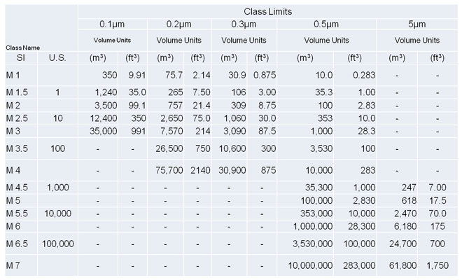
Figure 1 Level of cleanliness as defined by Fed-Std-209E.
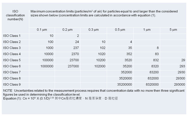
Figure 2 Level of cleanliness as defined by ISO-14644.
The level of cleanliness in a cleanroom is determined by its interior decoration and the configuration of air conditioning system. So it depends on what level of cleanliness the production process is trying to achieve when it comes to selecting appropriate configuration and airflow pattern. Based on the circulating airflow pattern, cleanrooms are classified into laminar flow type and disturbed (turbulent) flow type. The laminar flow has a single airflow direction, which can be used to take away dust particles. Since the single airflow direction can prevent dust particles from chasing and spreading, it can quickly remove dust particles and avoid accumulation of dust particles in the cleanroom. This is why cleanrooms with stricter demand of cleanliness will adopt the laminar flow type, while those with less strict demand of cleanliness will adopt the turbulent flow type, as shown in Figure 3.

To meet the production requirements, cleanrooms in a high-tech factory are designed with an electrical and mechanical framework that takes account of not only manufacturing machines and automatic production and transportation systems, but also high cleanliness air conditioning system, anti-static decoration, locally approved and UL’s (Underwriter Laboratories Inc.) fire protection system. Other systems include power, pure water, process cooling water, and dry oil-free compressed air for manufacturing, vacuum, chemicals supply, special gases supply, and FMCS (Factory Monitoring and Control System). When these systems work in tandem, they keep dust particles, temperatures, and humidity in the cleanroom in check. The necessary support systems for a cleanroom are shown in Figure 4.
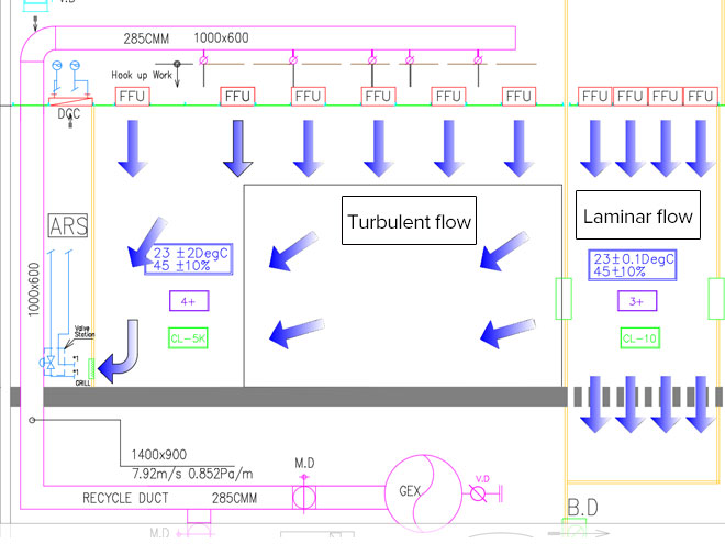
Figure 3 A schematic illustration of laminar and turbulent airflows.
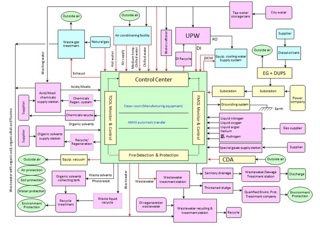
Figure 4 A map of necessary support systems for cleanrooms at high-tech plants.
The Procedure of Using RPA Software
Based on their uses and functions, cleanrooms can be roughly divided into two types: high-tech industrial cleanrooms and biomedical cleanrooms, which need to abide by different criteria and standards as described below.
(1) High-tech industrial cleanrooms
This type of cleanroom is commonly utilized for production or R&D in the electronic industry or the chemical industry. Due to the fact that such production and R&D are extremely sensitive to the influence of particles, gaseous chemical pollutants, space temperature, humidity, micro-vibration, electromagnetic interference, wavelength of light, and static electricity, cleanrooms are generally constructed with seismic-resistant reinforced concrete (RC) steel structure, with exterior walls constructed with metal sandwich boards. To make sure that production inside the cleanroom is free from exterior environment interference, the production areas are arranged towards the middle of the building as much as possible. If clean production happens to be near the exterior wall or general area, extremely airtight and dust-free metal board materials will be used as the cleanroom exterior layer to further isolate the room from the outside world, ensuring that it is free from external interferences.
(2) Biomedical cleanrooms
This type of cleanroom is commonly utilized for the production and R&D of ampoule, tablets, oral drugs, biological experimental research, and medical surgeries.

At present, the most widely adopted design standard for the pharmaceutical industry is the “European Union Guide to Good Manufacturing Procedure” (EU GGMP), developed by the European Union. Figure 5 shows the airborne particles classification standard, as suggested in the EU GGMP. Figure 6 shows the recommended limit for each grade of microbial contamination.
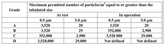
Figure 5 PIC/S GMP cleanliness definition
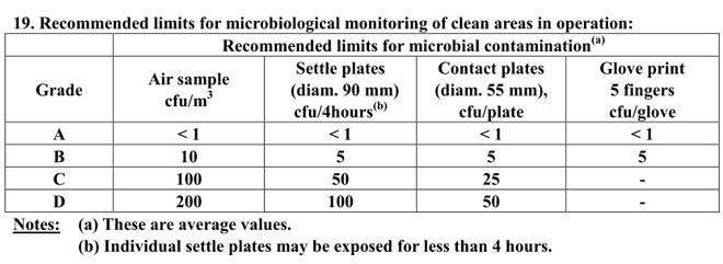
Figure 6 Recommended limits for microbiological monitoring in dynamic clean areas.
Trends and Prospects of Cleanroom Engineering
Cleanroom engineering faces many new challenges in response to the needs of industrial development. With the introduction of mini-LEDs that are capable of finer dimming and are smaller in size and structure, the trend is towards developing miniaturized and matrix LED display, and we expect to see LED unit become micro LEDs with sizes smaller than 100 micron in the future. Also, given that the semiconductor industry has already entered the nano-diameter era, it is clear that future cleanroom engineering challenges go far beyond controlling fine dust particles and airborne molecular contamination (AMC).

Apart from nano-grade size demands and energy saving requirements, another cleanroom development trend lies in factory service and equipment, which focuses on real-time monitoring and automation, and aims to establish high-efficiency management systems to reduce manpower. Currently, an automated process for replacing primary filters has become a common practice, which allows real-time monitoring of differential pressures and automatic replacement of clean filters to save manpower. The monitoring system will notify the factory staff to replenish new filters when the inventory is low. Presently, several big technology companies have adopted the Industry 4.0 concept and machine learning in achieving full automation and intelligent control of the chilled water systems.

On the other hand, cleanroom construction methods continue to progress. For example, in 2018 CTCI Group took on an 8K TFT LCD panel project in China for a large panel company. We went over construction method topics in detail, such as “automatic wind speed detection filter scanner,” “automatic floor cleaner,” and “Fan Filter Unit (FFU) filter test scanning.” Since the FFU filter test scanning can only be conducted during the later stage of cleanroom construction, the contractor must thoroughly inspect all HEPA and ULPA filters to ensure smooth operations. Moreover, due to the large scale of this electronics factory project and relatively short amount of time for construction, we had a tighter schedule that required us to complete leakage tests for tens of thousands of filters and other tests before the process equipment can be moved in. In the past, such work required massive amount of manpower working around the clock to fully scan-check the filter surfaces. Despite so, some places may be overlooked.

We joined hands with the owner and researched and developed a FFU leakage wind speed detection robot, which has the following functions:

1. Visual recognition: Through image processing, the FFU leakage wind speed detection robot can automatically identify the four corners of FFU equipment and mark them manually.
2. Automatic detection: The automatically or manually identified angular positions are then converted by the robot according to the coordinates to generate potential wind speed and leak test trace, so as to control the test equipment and perform testing and data recording.
3. CAD/BIM control: FFU information from CAD files are accessed, screened or selected from the system and submitted to the corresponding robot for detection purpose, and the FFU detection status is updated on the system once completed.
4. Background monitoring: As soon as the assigned testing is completed, the result is transferred to the background cloud via 4G/WIFI.

Engineering methods are advancing by leaps and bounds. The above-mentioned FFU robot is just one of the many innovations. Other inventions, such as automatic cleaning robots, floor coating robots, and transport robots, are still far from the production, but would become a reality for sure as labor costs gradually increase.
Applying Computational Fluid Dynamics to Cleanrooms
In addition to the automations mentioned above, computational fluid dynamics (CFD) is another key support to cleanroom engineering. From electronic products to semiconductors, CFD is widely adopted in the manufacturing process. For example, in the early stage of cleanroom planning and design, one can carry out an analysis of outside air flow field for the building to decide ideal locations for waste gas exhaust and fresh air entry, so as to prevent intrusion of polluted air either from outside or emitted internally. As for the cleanroom interior, CFD is used to simulate airflow and heat transfer in areas of manufacture where products may be prone to environmental pollutions.

In the case of 8K TFT LCD panel project, the original air conditioning framework for the etching area in the cleanroom is RCU+FFU (Recycled air handling unit + Fan Filter Unit) system. We suggested the client to drop the FFU and opt for just the RCU instead. The change is indicated in Figure 7, where on the left-hand side is the original system, and the right-hand side the new system. Figure 8 shows the schematic relationship between production equipment and ambient airflow.
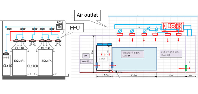
Figure 7 The left-hand side is the original system, and the right-hand side is the new system
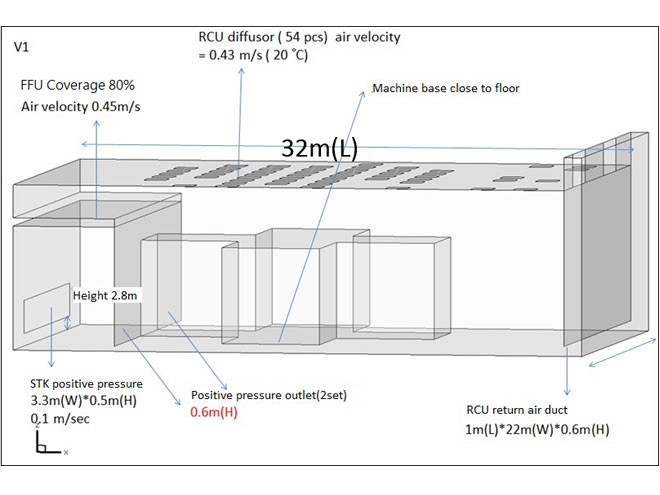
Figure 8 The schematic relationship between production equipment and ambient airflow
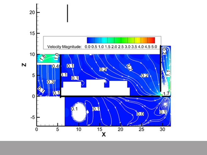
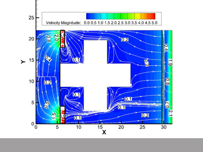
We used ANSYS Fluent software to carry out CFD ambient air temperature simulations for the new etching area plan in collaboration with National Taipei University of Technology. The first CFD simulation on May 15, 2018 showed that the airflow streams were not even nor smooth, and are coupled with serious air vortexes, as indicated in Figure 9 and 10.
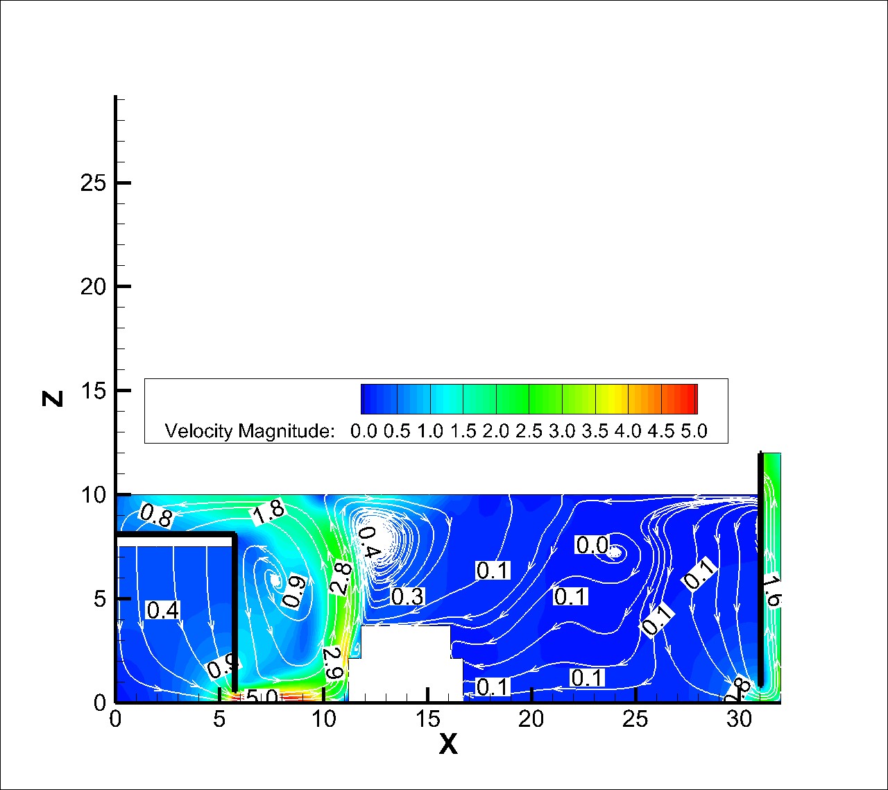
Figure 9 Airflow distribution section diagram (showing the locations of vortex and no wind).
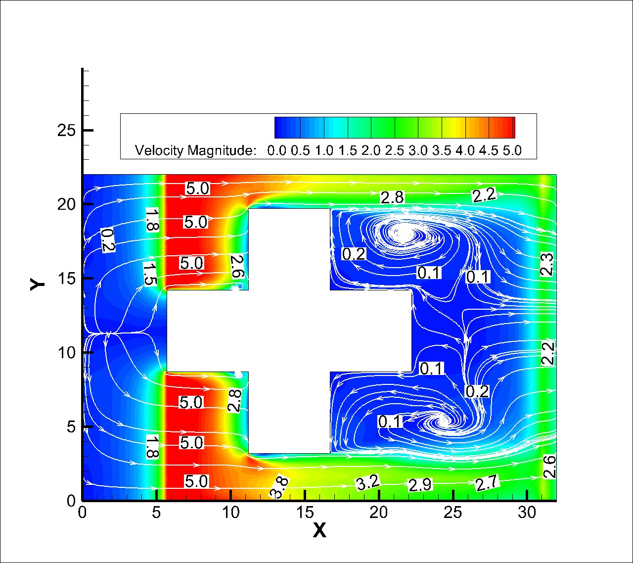
Figure 10 Airflow distribution plan (showing the locations of vortex and no wind).
After reviewing the causes of uneven airflow and vortex, we installed additional return air ducts and increased floor openings leading to the SUB FAB, which improved the airflow. The adjustment is shown in Figure 11 and Figure 12.
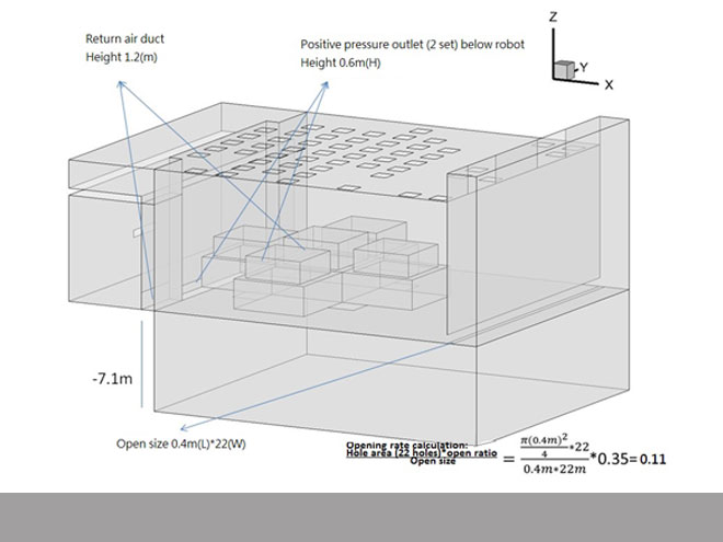
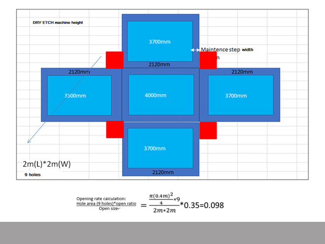
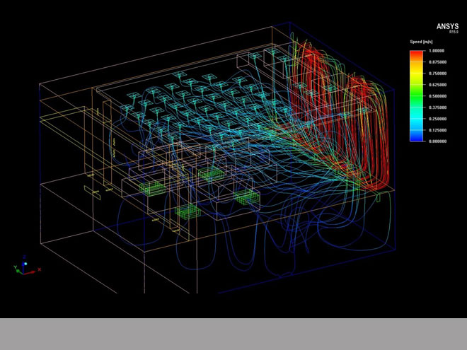
Figure 13, Figure 14, and Figure 15 show the results of CFD simulation of the improvement plan put forward on 20 June 2018. By adding return air ducts and openings to guide the airflow, airflows finally become smoother. The owners and technical units assessed the results and approved this modification plan.
Conclusion
Just as technologies are constantly advancing, cleanroom engineering is also evolving. Different industries have different production processes, and it is necessary to understand their needs and characteristics, catch up with the changes in advanced process, so that we can successfully design and deliver projects that meet the needs of the industry.

From what we saw earlier in this article in terms of CFD applications, simulation has a couple of advantages: assessment of engineering design in advance, predicting the effectiveness of recommended design, and revealing the overlooked details. Thanks to CFD, we can better evaluate the system’s operation in the future and come up with more rigorous and sound designs, providing the owner with the most reliable engineering services.
References
United States Federal Standards Fed-Std-209E
International Organization for Standardization ISO 14644
PIC/S: Guide to Good Manufacturing Practice for Medicinal Products