Technology
技術分享
CFD Analysis of Hot-Air Recirculation Affection in Air-Cooled Heat Exchanger
— Chung-Cheng Chen, Principal Equipment Engineer, CTCI Mechanical & Equipment Engineering Department, GEB
In an effort to improve the quality of offerings in global project execution, CTCI has entered into a one-year industry-academia cooperation agreement in 2017 with the National Taiwan University of Science and Technology to optimize air-cooled heat-exchangers widely used in heat-exchange equipment of refineries, petrochemical plants, power plants, etc. Employing CFD (Computational Fluid Dynamics) software, and combining CTCI's project practice information and drawings, the air circulation of air-cooled heat-exchangers in different environments is simulated, and the root cause of hot-air recirculation is identified. It generates the most suitable configuration to improve the program to ensure maximum effectiveness, standardize the optimal configuration, and provide the most reliable engineering service to its customers.
Industry-Academia Cooperation Achieves Air-Cooled Heat-Exchanger Efficiency Optimization
Air-cooled heat exchanger (Figure 1) is one kind of heat-exchange equipment widely used in petroleum, petrochemical, natural gas and other industries for cooling purposes. It’s mainly composed of tube bundles, header, fans, louvers and support rack. In contrast to water-cooled system, which consists of a traditional shell-and-tube heat exchanger and a cooling tower, it uses ambient air as the main cooling medium, and the air is blown outside the bundle to cool the higher-temperature process fluid in the tube to the desired operating temperature. This procedure does not require a large amount of industrial water, and is suitable in areas under geographical restrictions, and in places lacking water resources or with water-saving needs.
Figure 1. Air-Cooled Heat Exchanger.
While executing international engineering projects, CTCI often gets requests for flow-field analysis of the location of the air-cooled heat exchanger to plan height and orientation of the installation, and if it would lower the efficiency of the air-cooled heat exchanger and affect the overall operational performance of the system.

However, quite a few factors play a role in hot-air recirculation. Ambient air temperature, external wind direction/speed and the height/distribution of the surrounding buildings are the most influencing factors. Among them, environmental wind direction and speed are the forces of nature that human beings cannot control. Finding the most suitable configuration and improved measures to ensure that the heat-exchange efficiency of the whole system meets the operational requirements under wind direction and speed in different seasons is an engineering design issue.
CFD Simulation Analysis Process
CFD simulates the air circulation by evaluating the complete flow-field characteristics, such as speed and temperature, and then provides charts to visualize the flow field (Figure 2) to carefully analyze and determine the cause of hot-air recirculation; it provides various options for improvement as also relevant numerical model geometry. A systematic simulation suggests the effectiveness of improvements made to assess the impact of important parameters, prevent hot-air recirculation, and maximize the equipment’s operational efficiency.
After simulation analysis of performance and characteristics of air-cooled heat exchanger, the data is entered into the environmental flow field for overall numerical simulation as per the characteristics of seasons or configurations. The method enables the simulation of actual flow field, and the flow of hot air in the flow field of overall space is assessed and the hot-air recirculation is optimized to improve performance. The complete simulation analysis is shown in Figure 3.
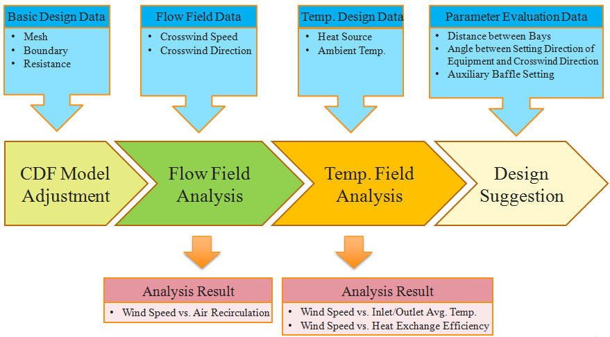
Figure 3. Simulation Analysis Work Flow Chart.
CFD Model Formulation
In the overall field area, the location, height, wall size, direction of entry and exit access, and relative position of each building will affect one another. Similarly, there will be an indirect effect on the air-cooled heat exchanger. The environmental boundary conditions are first affected by the building, which in turn affect the operational performance of the air-cooled heat exchanger. Since the hot air will move vertically due to thermal buoyancy and pressure, the air-cooled heat exchanger will discharge the air upwards, which will be blown away by the crosswind. Therefore, it is important to consider the influence of the boundary condition when there is an external flow wind direction.

Take an EPC project in a refinery in Southeast Asia as an example. As shown in Figure 4, the air-cooled heat exchanger is located in the Main Building, M. M is a steel structure. Its sides do not have solid walls. Most of them are open spaces with grating floor. Wind resistance by grating floor is also reflected in the boundary conditions.

When establishing the CFD analysis model, in addition to the main building, M, where the air-cooled heat exchanger is located, buildings with large surrounding areas, which will affect the overall flow field, should also be included in the simulation, such as Side buildings A and B. The two buildings have solid walls, so will obstruct the air from flowing freely, and thus have a great influence on the flow field. However, small buildings will be ignored due to negligible effect on the flow field so as to lower simulated resource loading. Further, any irrelevant factors that may affect the rapid convergence of the overall simulation will be deleted from the analysis model.
Figure 4. Factory Model Illustration.
Numerical Analysis
1. Flow Field—Velocity field
After the boundary condition of the steady flow field is set and the turbulence module calculation and calculation are complete, the flow field can be observed as per simulation. The ideal condition of the exhaust air is upward vertical. However, the flow vector diagram in Figure 5 shows a scattering air outlet through the fan in the air-cooled heat exchanger. When it closes at the exit, the speed is higher and the cross-sectional area is smaller, whereas farther away from the exit, the speed is slower and the cross-sectional area larger. When the two fans are too close, the airflow lines, which are scattered, will be affected, generating turbulent flow and the hot air discharged will be sucked in again by the adjacent fan, and is again sucked into the air-cooled heat exchanger resulting in air-recirculation phenomenon.
Figure 5. Flow Vector Diagram.
2. Temperature Field
To quantify the CFD numerical analysis, the variation in temperature by the known flow-field phenomenon and the energy condition are inputted, thus the temperature distribution map around the building is generated, as shown in Figure 6. The gradient of temperature field compares with flow-field diagram. When the flow field is disturbed, turbulent and vortex are generated. Most of the temperature rise in the temperature observation is obvious, especially when the average flow velocity in the region is slow. The accumulated heat will not disperse easily, and the temperature rise is particularly obvious.
Figure 6. Gradient of Temperature Field.
Parameter Affection Assessment
By inputting different control parameters, the variation in temperature field state can be monitored to observe the trend in air-cooled heat exchanger performance conversion, which can be used as reference for auxiliary air-cooled heat-exchanger installation planning/improvement.

1. Wind Speed Assessment
Various crosswind speeds are compared with windless state. The change in temperature influence can be seen in Figure 7. At low wind speed, the temperature of the inlet/outlet accesses rises gradually. As the wind speed continues to rise, the temperature rise trend is reversed, which tends to be stable. The accumulated heat- dissipation performance of air-cooled heat exchanger changes, showing a small fluctuation in a range, as shown in Figure 8.
Figure 7. Inlet/Outlet Temperature Rise Ratio of Air-Cooled Heat Exchanger under Various Crosswind Speed States.
Figure 8. Accumulated Heat-Dissipation Rate Change of Air-Cooled Heat Exchanger under Various Crosswind Speed States.
2. Evaluation of The Distance between Bays
The outlets of air-cooled heat exchanger stand adjacent to one another, and the hot air discharged by the fans may collide with each other to cause a chaotic flow field, increasing the chance of hot-air recirculation. As shown in the flow vector diagram of Figure 9, if the spacing between bays can be moderately controlled, a better heat- dissipation effect can be expected.
Figure 9. Flow Vector Diagram under Different Distances between Bays.
3. Assessment of Angle between Setting Direction of Equipment and Crosswind Direction
When planning air-cooled heat-exchanger setting direction, the wind rose diagram should be referred to (regional wind direction/wind speed distribution percentage map) to obtain the most favorable conditions for equipment operation and avoid the air discharged from the upstream air outlet being sucked by the downstream fan, and thus avoid increasing the probability of hot-air recirculation. The influence of crosswind direction on the average temperature of the air-cooled heat exchanger outlet is shown in Figure 10.
Figure 10. Comparison of Crosswind Direction Affection on Average Outlet Temperature of Air-Cooled Heat Exchanger.
4. Auxiliary Baffle Setting
When the outlet/inlet auxiliary baffles of air-cooled heat exchanger are arranged, the hot air discharged between the bays does not interfere to form a chaotic flow field. By doing this, it will reduce the hot-air recirculation phenomenon and exhibit better heat- dissipation effect. The evaluation data is shown in Figure 11.
Figure 11. Comparison of Outlet Temperature of Air-Cooled Heat Exchanger with Auxiliary Baffle.
Conclusion
Through industry–academia cooperation with the National Taiwan University of Science and Technology, CFD was employed to simulate the air-circulation status, and by calculating the complete flow field characteristics, such as speed and temperature, various models of the flow field can be visualized. A systematic study of different environmental variables enables us to assess the feasibility of various improvement options for air-cooled heat exchanger setting, which can be used for reference to plan, review and improve the project before, during and after implementation, and thus air-cooled heat exchanger can provide the maximum benefit. Guidelines established by the simulation results can be used to assess the phenomenon of the flow field in each air-cooled heat exchanger. The design reference document can be used to effectively manage and analyze the flow-field analysis results of the contractor.